Page 1 of 3
Ongoing Saga of the LC Electrical Gremlin
Posted: Wed Jan 20, 2016 1:58 pm
by pkay
Some of you who care to remember may recall that after a gearbox bearing collapse saw me remove and reinstall the engine on my LC only for there to be no spark, well the problem persists. So I have replaced the coil, checked the kill switch which is OK, there is current to and from the CDI. And I have replaced the plugs, Next?????????????
Any help greatly appreciated.
Re: Ongoing Saga of the LC Electrical Gremlin
Posted: Wed Jan 20, 2016 2:59 pm
by hybrid
If you have an analogue multi meter, you could put it on the pickup and see if it registers voltage?
Re: Ongoing Saga of the LC Electrical Gremlin
Posted: Wed Jan 20, 2016 4:10 pm
by JonW
Im wondering if the stator is grounded properly. As Jeff says, you need to see if you get a trigger from the pickup, that tells the CDI to spark the plugs. If thats working then youre not getting the voltage to the coil I would think.
Re: Ongoing Saga of the LC Electrical Gremlin
Posted: Wed Jan 20, 2016 8:25 pm
by ged
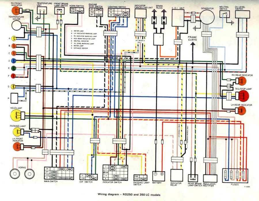
I can remember scratching my head over that LC wiring diagram 20 years ago. It's bloody hopeless.
Have you checked continuity of each conductor on the 3 connector blocks coming from the engine? Just because they're connected doesn't mean they're conducting. Jam a multimeter probe down the back of each wire on either side of the block to make sure they're actually connected electrically.
There's also an earth on the case in there someplace too.
Re: Ongoing Saga of the LC Electrical Gremlin
Posted: Fri Jan 22, 2016 2:57 pm
by pkay
Thanks Guys - I know it has to be something simple with a circuit somewhere and something I've overlooked putting the engine back in. Earths are the most likely answer of course. I'll give these a go and see what happens.
Wish me luck
Re: Ongoing Saga of the LC Electrical Gremlin
Posted: Wed Jan 27, 2016 2:23 pm
by pkay
So another update and another question.
I was going back over the wiring and checking the currents etc. Now from the CDI there are three wires - an orange one that goes to the coil. A black white one that connects to the kill switch. And a black one which is earth, When the bike is kicked the pulse goes through the black white wire. Is this correct?
Re: Ongoing Saga of the LC Electrical Gremlin
Posted: Wed Jan 27, 2016 2:45 pm
by hybrid
From memory, the kill switch earths the black and white wire to kill the ignition.
The orange one should be the actual discharge to the coil I think (they are orange on the 500).
Re: Ongoing Saga of the LC Electrical Gremlin
Posted: Wed Jan 27, 2016 5:57 pm
by JonW
pretty sure orange is the trigger on the LC, but ive not got the diagram with me... i do know its different in the later ypvs models (unhelpful i know)
Re: Ongoing Saga of the LC Electrical Gremlin
Posted: Wed Jan 27, 2016 6:41 pm
by hybrid
I've got the tank off the LC.. I could just have a look

Re: Ongoing Saga of the LC Electrical Gremlin
Posted: Thu Jan 28, 2016 8:44 am
by ged
Just a completely technical point PK, but important anyway. If your testing with a multimeter your detecting voltage rather than current, which you would measure by putting your probes in series, rather than testing between a conductor and ground? Just so we're all on the same page.
The wiring diagram shows that there should be 3 sets of wires coming from the 'generator'. The 3 phases of the charging circuit, the red and black going to the cdi (which should be the charging circuit regulation) plus a third white wire with red bands, which should be the pulse trigger.
I'd try and verify that you have each if those in place correctly.
Re: Ongoing Saga of the LC Electrical Gremlin
Posted: Thu Jan 28, 2016 2:35 pm
by pkay
Yup
So the red and black from the generator is the one that has the current on kick over. The white ones (three of them) go to the right point and the red white one is the rectifier wire that connects with it's cousin.
So Hybrid what did you find with yours?
Re: Ongoing Saga of the LC Electrical Gremlin
Posted: Thu Jan 28, 2016 3:00 pm
by hybrid
I didn't look. I can have a look today when I get home.
Is there anything in particular you want me to look at?
I'm running Zeeltronic, but the wiring should still be pretty stock as I'm using the stock CDI. The Zeel just intercepts the signal from the pickup.
Re: Ongoing Saga of the LC Electrical Gremlin
Posted: Fri Jan 29, 2016 9:21 am
by ged
pkay wrote:Yup
So the red and black from the generator is the one that has the current on kick over. The white ones (three of them) go to the right point and the red white one is the rectifier wire that connects with it's cousin.
So Hybrid what did you find with yours?
I think you'll find that the red/white is the ignition trigger pulse. That's where you would need to find a voltage output.
When hybbie checks his Zeeltronic, that should tell us.
Rectification of the 3 phase ac output (white wires) to dc is all happening within the cdi. The red and black wires should be controlling the stator field coil intensity- voltage regulation.
Re: Ongoing Saga of the LC Electrical Gremlin
Posted: Mon Feb 01, 2016 10:44 am
by pkay
Roger that - I'll check what is happening on that one.
Thanks for the tip
Re: Ongoing Saga of the LC Electrical Gremlin
Posted: Mon Feb 01, 2016 6:32 pm
by hybrid
White with red trace is definitely the one spliced for the zeeltronic (yellow and brown wires), so it's your trigger wire.
I've also connected that one to my aftermarket tacho.

